A Network Primer
Internetworking
-
A computer network is a communication system for connecting end-systems. We often refer to end-systems as hosts. Some hosts on a computer network are dedicated systems, such as printers or file servers, without any capabilities for interactive users.
-
LAN, or Local Area Network, connects computer systems that are close together--typically within a single building, but possibly up to a few kilometers apart. Popular technologies for LANs are Ethernet and token ring.
LANs typically operate at high speeds--an Ethernet operates at 10 Mbps (million bits per second) while IBM's token ring operates at both 4 Mbps and 16 Mbps. Another LAN technology, FDDI (Fiber Distributed Data Interface), use fiber optics and have a data rate of 100 Mbps.
Interface CardEach computer on a LAN has an interface card of some form that connects it to the actual network hardware. (Be aware that raw network speeds are usually not realized in actual data transfers.)
-
A Wide Area Network or WAN connects computers in different cities or countries.
SynonymWANs are sometimes referred to as long haul networks.
A connection technology for WANs is leased telephone lines operating between 9600 bps (bits per second) and 1.544 Mbps.
-
Between the LAN and WAN is the Metropolitan Area Network or MAN. These cover an entire city or metropolitan area and frequently operate at LAN speeds.
Common technologies are coaxial cable (similar to cable TV) and microwave.
-
An internet or internetwork is the connection of two or more distinct network so that computers on one network are able to communicate with computers on another network.
Goal of InternetThe goal of internetworking is to hide the details of what might be different physical networks, so that the internet functions as a coordinated unit.
One way to connect two distinct physical network is to have a gateway that is attached to both networks. This gateway must pass information from one network to the other. It is sometimes called a router. Consider the figure below.
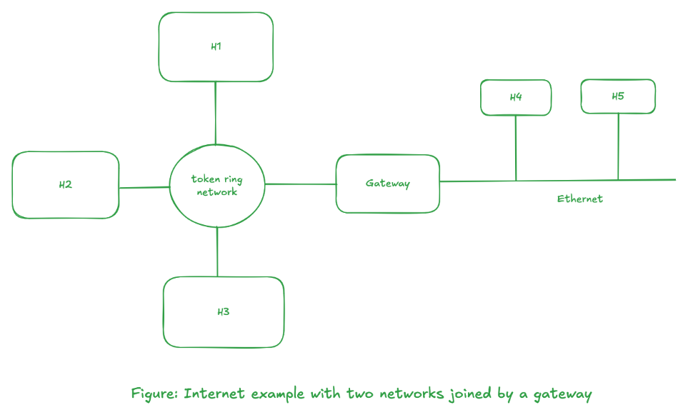
There are three hosts on the token ring, H1, H2, and H3, and two hosts on the Ethernet, H4, and H5. This is a gateway between the two physical networks, and it must contain an interface card to attach to the token ring network and another interface card to attach to the Ethernet.
Interconnection Terminologies
-
The term we used to describe the interconnection depends on the layer in the OSI model at which the connection takes place.
-
Repeaters operate at the physical layer (layer 1) and typically just copy electrical signals (including noise) from one segment of a network to the next. Repeaters are often used with Ethernets, for example, to connect two cable segments together to form a single network.
-
Bridges often operate at the data-link layer (layer 2) and they copy frames from one network to the next. Bridges often contain logic so that they only copy a subset of the frames they receive.
-
Routers operate at the network layer (layer 3). The term router implies that this entity not only moves information (packets) from one network to another, but it can also make decisions about what route the information should take.
-
Gateway is a generic term that refers to an entity used to interconnect two or more networks. In the TCP/IP community, the term gateway refers to a network level router.
gatewayThe term gateway is sometimes used to describe software that performs specific conversions at layers above the network layer.
HW/SWRepeaters are usually hardware devices, while bridges and routers can be implemented in either hardware or software. A router (gateway) is usually a dedicated system that only does this function. 4.2BSD, however, was the first general-purpose system that could also operate as a gateway.
-
-
An internet of computer networks is similar in principle to the international long distance telephone service that is available today. Telephones are connected to local phone company, which in turn is connected into a national long distance network, which is then connected into an international network. When you direct dial an international call, this "telephone internet" hides all the details and connects all the telephones into a coordinated unit. This is the goal of an internet of computer networks.
-
A host is said to be multihomed if it has more than one network interface. For example, a host with an Ethernet interface and a token ring interface would be multihomed.
Looking at the different levels of abstraction, we go from a user sitting at a terminal to an internet.
- Users login to a host computer.
- Host computers are connected to a network.
- Networks are connected together to form an Internet.
OSI Model, Protocols, and Layering
-
The computers in a network use well-defined protocols to communicate. A protocol is a set of rules and conventions between the communicating participants.
Since these protocols can be complex, they are designed in layers, to make their implementation more manageable. Figure below shows the OSI model.
        +--------------+
      7 | Application  |
        +--------------+
      6 | Presentation |
        +--------------+
      5 | Session      |
        +--------------+
      4 | Transport    |
        +--------------+
      3 | Network      |
        +--------------+
      2 | Data Link    |
        +--------------+
      1 | Physical     |
        +--------------+

        Figure: OSI model
This model, developed between 1977 and 1984, is a guide, not a specification.
-
OSI provides a framework in which standards can be developed for the services and protocols at each layer.
Protocol Suite ComparisonLater, we will compare the layers for these actual networks (TCP/IP, XNS, SNA, etc...) against the OSI model, but realize that no network is implemented exactly as the OSI model shows.
-
Layering provieds well-defined interfaces between the layer, allowing changes to be made without affecting other layers.
Protocol SuiteEach layers contains its own protocol. A protocol suite is a collection of protocols from more than one layer that forms the basis of a useful network.
Different protocol suites have different protocols at different layers. -
The figure below shows a model for two systems that are connected with a network.
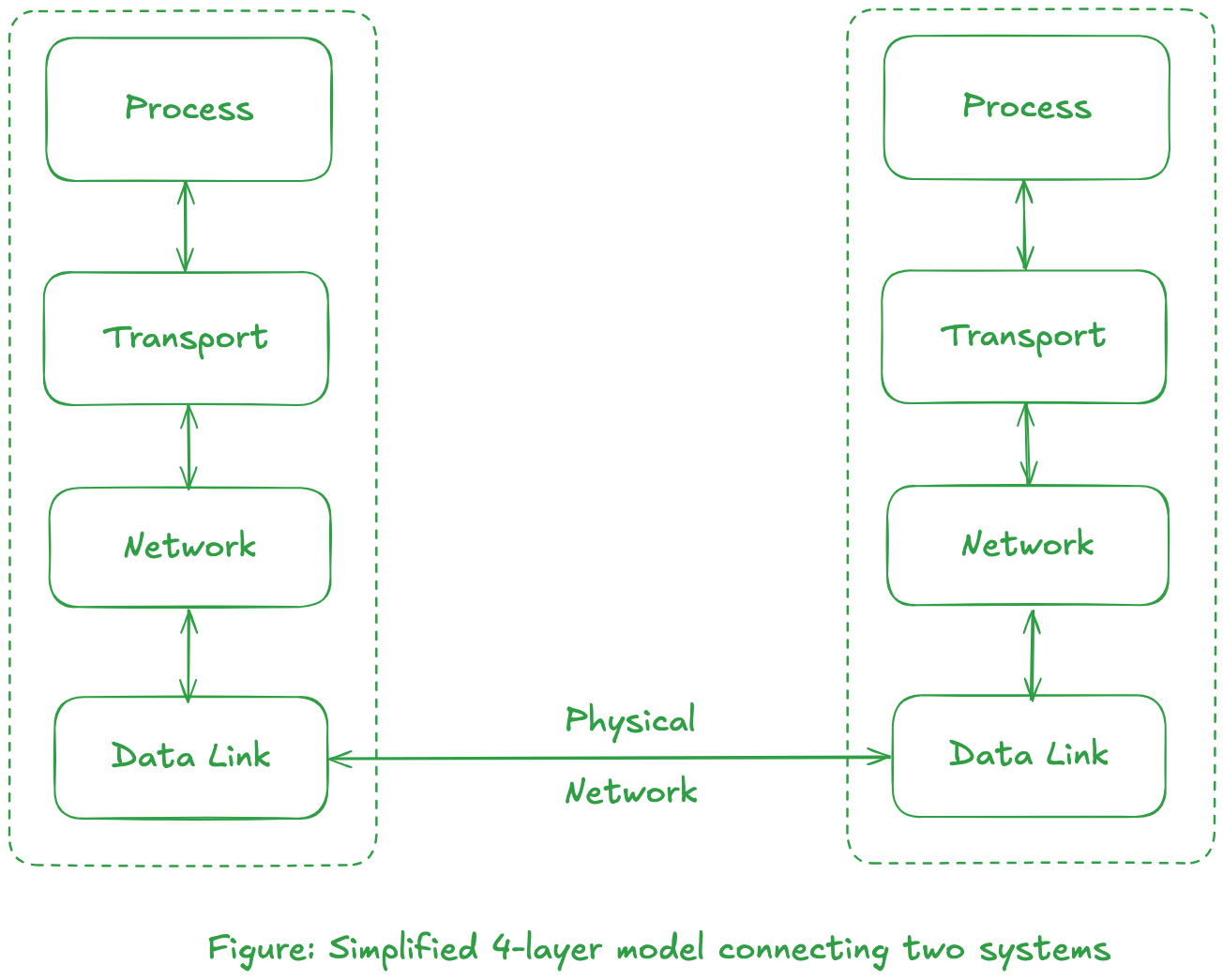
In the figure above, two boxes called transport layer and the network layer define a protocol suite.
AbstractionThe multiple layers that define the network and hardware characteristics (Ethernet, token ring, etc.) are grouped together into our data-link layer.
An application program exist at the process layer.
-
Consider a program whose task is to transmit data file over a network. The program, in its simplest form, would have to create a sub-system which would send/receive "message" that is of pre-defined format. The Internet Protocol suite defines the message format for low level network layers interfaces required for interface device drivers.
In regards to previous figure, an application would need to send and receives messages through use of transport protocol such as UDP (User Datagram Protocol) or TCP (Transmission Control Protocol), which in turn uses IP (Internet Protocol), to exchange data with the other host. An example of this would be Trivial File Transfer Protocol or TFTP.
-
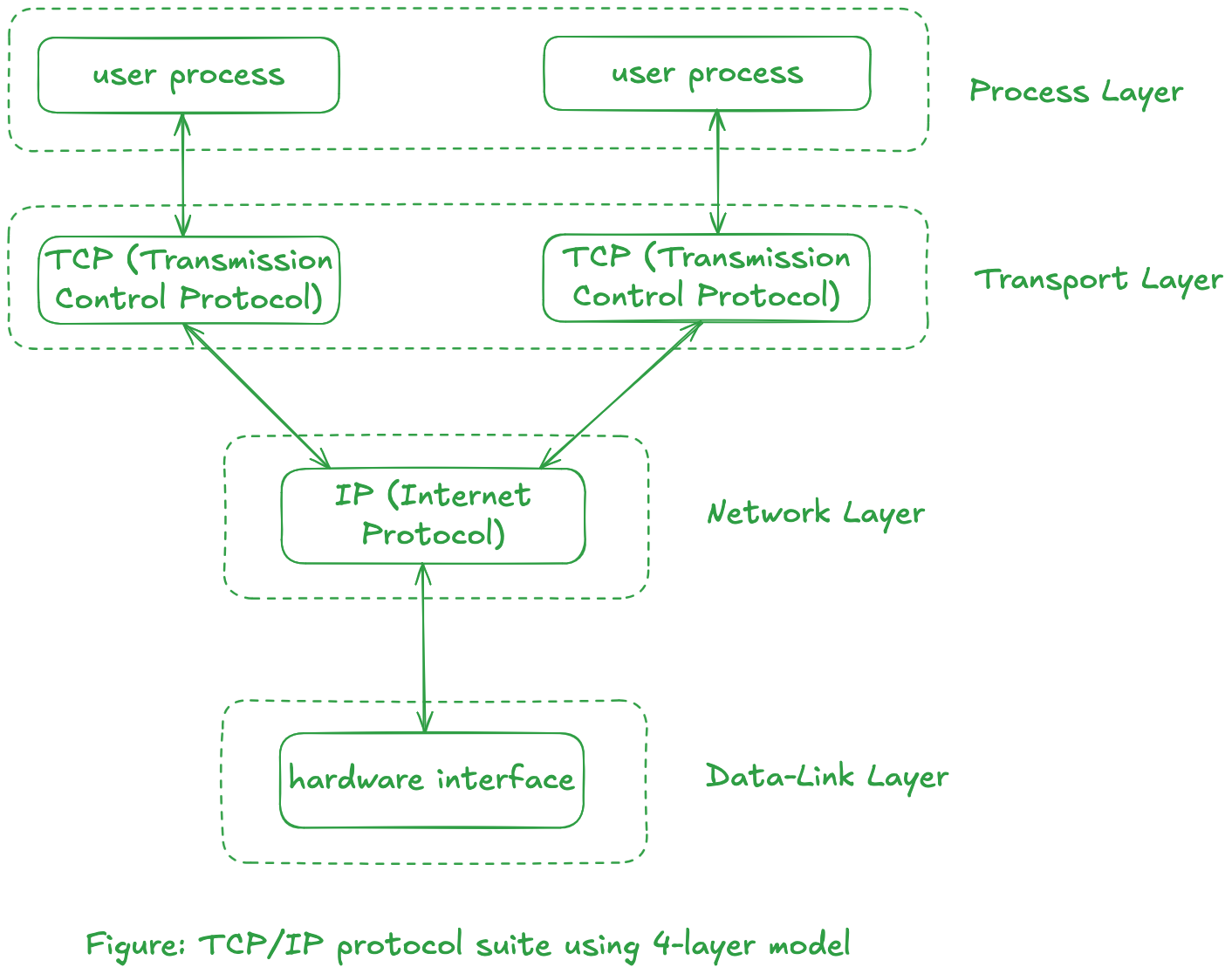
The flow of communication with different layers for TCP/IP using the simplified 4-layer model is shown below.
-
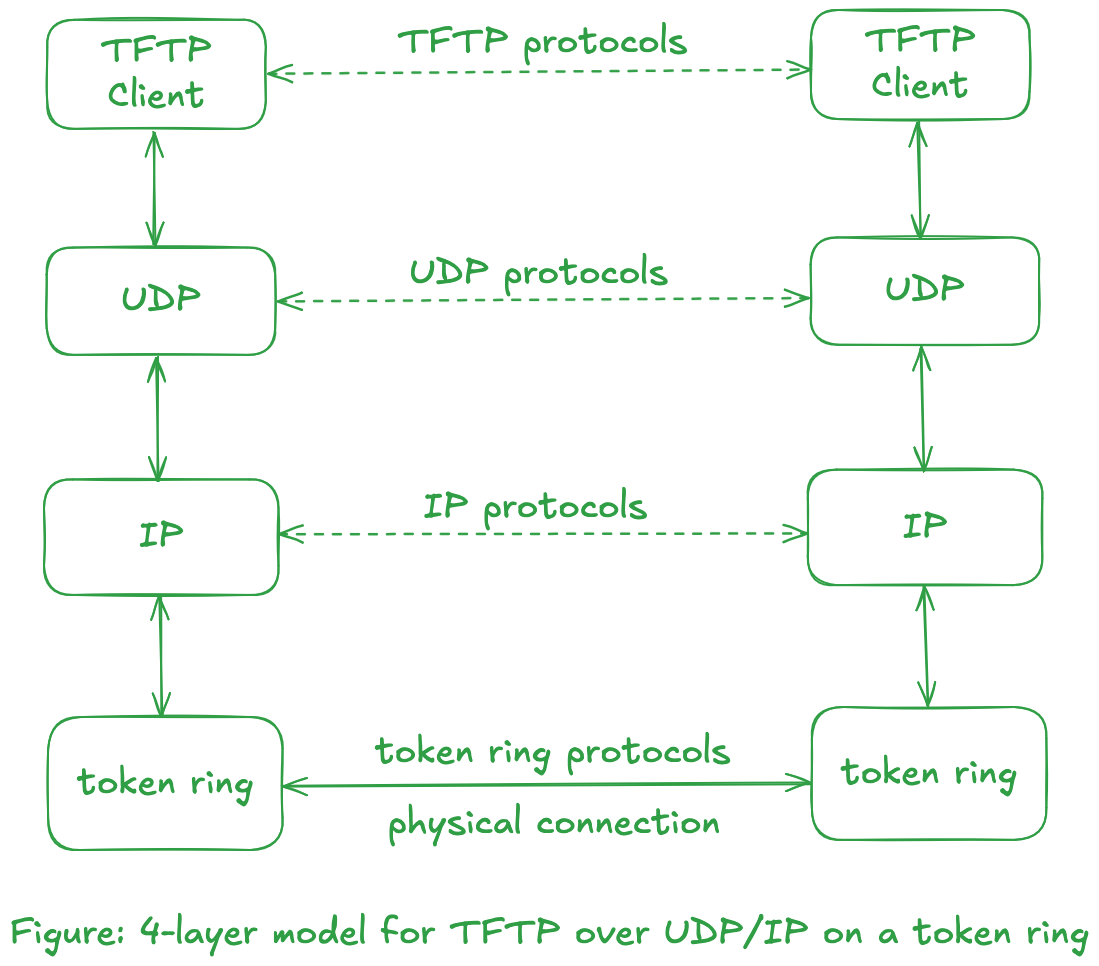
Consider two hosts connected with an Ethernet uses an application that uses TFTP. The 4-layer model will be as follows:
 Symbolic Representation
The top three boxes shows dashed line to indicate that those layers communicate "virtually" with each other using the indicated protocol. Only the loweest layer physically communicate with each other.
The horizontal lines between layers at the same level is known as peer-to-peer protocols.The flow of data will be from the TFTP box from one side down to its UDP box, down to the IP box, and down to the Ethernet box which is sent across the physical link to the other side and up.
-
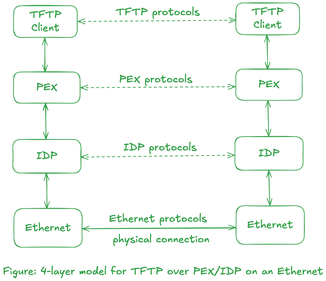
One of the advantage of layering--beside making the protocol suite easier to understand--it to allow us to replace the contents of a layer with something else with similar functionality. For example, if the physical layer comprises of token ring network, the diagram would be as follow:
Notice that TFTP protocols did not change, nor did transport protocol UDP and network protocol IP.
This illustration can be taken a step further by replacing the middle two boxes that use UDP/IP with the TCP/IP protocol suite, or with boxes that use PEX/IDP protocols from the Xerox NS protocol suite. The figure below illustrates use of Xerox NS protocol suite over Ethernet.
Network Byte Order
-
Before moving towards network byte order, we need to know how computers store numbers in memory. Consider that we need to store a number in an variable of type unsigned integer for 32 bits. Assume that we have to store the number
305419896. The format in bits will be as follows:3 2 1
1 0 9 8 7 6 5 4 3 2 1 0 9 8 7 6 5 4 3 2 1 0 9 8 7 6 5 4 3 2 1 0
+-+-+-+-+-+-+-+-+-+-+-+-+-+-+-+-+-+-+-+-+-+-+-+-+-+-+-+-+-+-+-+-+
|0|0|0|1|0|0|1|0|0|0|1|1|0|1|0|0|0|1|0|1|0|1|1|0|0|1|1|1|1|0|0|0|
+-+-+-+-+-+-+-+-+-+-+-+-+-+-+-+-+-+-+-+-+-+-+-+-+-+-+-+-+-+-+-+-+The question now is, how should the addressing be done? The lowest addressable field in a computer is a byte--sometimes called a character. This means a computer can uniquely identify a byte in the memory location. A computer can store an unsigned integer of 32-bits/4-bytes where it stores the Most Significant Byte or MSB at the higher byte address (thus making the Least Significant Byte or LSB being stored at the lower byte address). The opposite can also happen, i.e., MSB stored at lower byte address and LSB stored at higher address. The former is called as Little Endian while the latter one is called Big Endian.
The code fragment below illustrates the property described above.
endianness.c#include <stdio.h> /* for fprintf, and stdout */
#include <stdint.h> /* for uint8_t and uint32_t */
union bo_uint32_t { /* bo -> Byte Order */
uint8_t arr[4];
uint32_t whole;
};
#define bo_first arr[0]
#define bo_second arr[1]
#define bo_third arr[2]
#define bo_fourth arr[3]
#define bo_whole whole
typedef union bo_uint32_t bo_uint32_t;
int main (void) {
bo_uint32_t foo;
foo.bo_whole = 0x12345678;
fprintf(stdout, "The value of foo is: 0x%X\n", foo.bo_whole);
fprintf(stdout, "Element 0 (addr = %p) has the value: 0x%x\n",\
&(foo.bo_first), foo.bo_first);
fprintf(stdout, "Element 1 (addr = %p) has the value: 0x%x\n",\
&(foo.bo_second), foo.bo_second);
fprintf(stdout, "Element 2 (addr = %p) has the value: 0x%x\n",\
&(foo.bo_third), foo.bo_third);
fprintf(stdout, "Element 3 (addr = %p) has the value: 0x%x\n",\
&(foo.bo_fourth), foo.bo_fourth);
return 0;
}The output will be of the form:
$ ./endianness
The value of foo is: 0x12345678
Element 0 (addr = 0x16f166ed8) has the value: 0x78
Element 1 (addr = 0x16f166ed9) has the value: 0x56
Element 2 (addr = 0x16f166eda) has the value: 0x34
Element 3 (addr = 0x16f166edb) has the value: 0x12
Here we can observe that the MSB--
0x12in this case--is stored in higher byte address. This shows that the system uses little endian. This is not surprising as most modern system uses this endianness.UnionThis is also one of the use case of
unionprovided by the C language. One of the characteristics ofunionis that the size of the union will be the size of the largest member in the union. This allows us to view data in different format. -
Unfortunately, not all computers store the bytes that comprise a multibyte value in the same order.
Bytes and OctetsSome networking literature uses the term octet, which means an 8-bit quantity of data. The term octet is used cause some computer systems, notably the DEC-10 series and the Control Data Cyber series, don't use 8-bit bytes. Fortunately, most modern systems use 8-bit bytes, so we'll use the term byte.
Network protocols specify their network byte order. The TCP/IP, XNS, and SNA protocols all use the big endian format for the 16-bit integers and 32-bit integers that they maintain in the protocol headers. (Fortunately, the protocols maintain only integer fields--such as source address, port, etc--as the differences in the internal formats for floating point data are even worse.)
-
UNP: Consider a 16-bit integer that is made up of 2-bytes. There are two ways to store this value: with the low-order byte at the starting address, known as little endian, or with the high-order byte at the starting address, known as big endian.
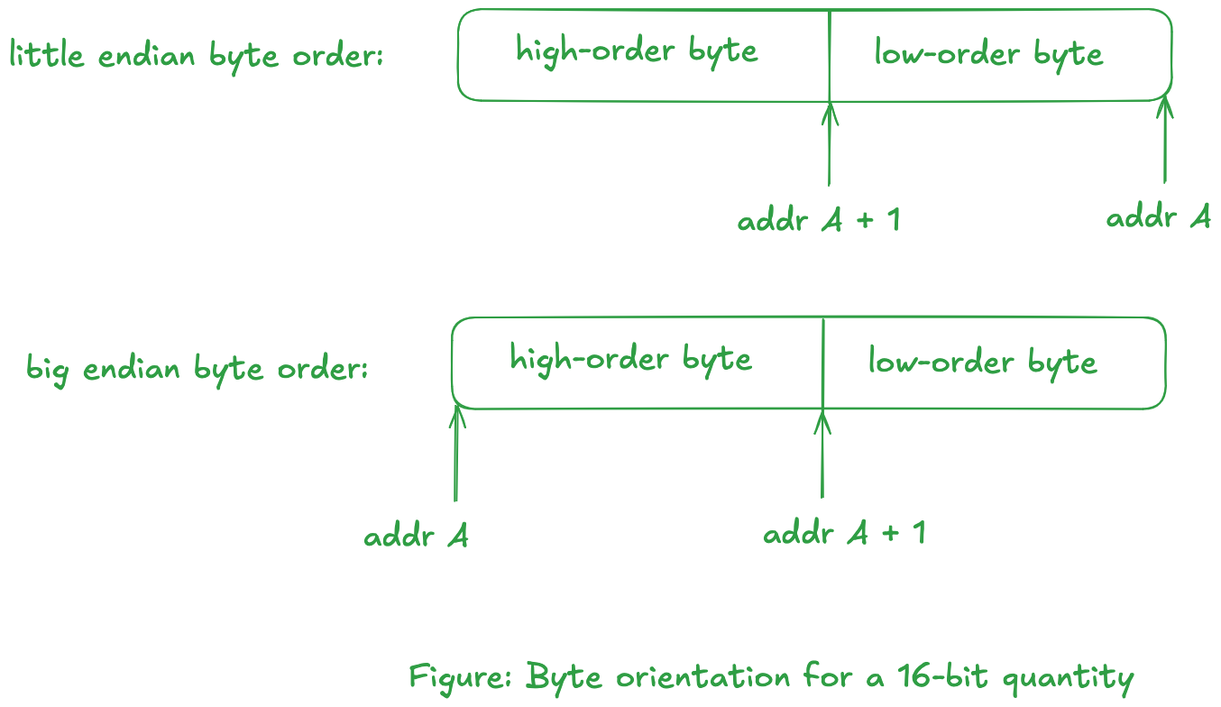
In Little Endian, we are looking at increasing memory address going from right to left. The reason behind this byte ordering is that a lower address implies a lower order byte.
In Big Endian, we are looking at increasing memory address going from left to right.noteUNP mentions that:
The byte ordering with 32-bit integers are even worse, as some systems swap the two 16-bit pieces of the 32-bit integer.
-
The protocol has no control over the format of the data that the applications transfer across the network--the protocol only specifies the format for the fields that it maintain.
Encapsulation
-
The data flows through protocol suite and transferred over a network, with each layer adding it's own "control information". Consider a simple application which uses it own protocol. The application has a clear definition of what sort of data is expected, which is possible by reserving the first (say) 10 bytes of data. This means that the application anticipates a message which is at least 10 bytes long.
cautionMost user-level application need not worry about the message encapsulation fields (apart from some such as Internet addresses and port) for lower level protocols such as the transport layer protocols (TCP/UDP), network layer (IP), and data-link layer (Ethernet, ...) as the OS handles this for us. This implies data transmission/reception excludes the control information for lower level protocols. A superuser can override this default behavior by constructing their own control information and adding it to the original data message. (Not entirely sure about data-link layer protocol tho.)
Creating your own protocol means defining your own "small" control information header which is included in the message.
The entire message--including the custom 10 bytes control information--is encapsulated into another "message" for the layer below it. We define the unit of information that are passed along a network based on layer at which the transfer is taking place as:
    +--------------+
  7 | Application  |    message
    +--------------+
  6 | Presentation |    message
    +--------------+
  5 | Session      |    message
    +--------------+
  4 | Transport    |    message
    +--------------+
  3 | Network      |    packets
    +--------------+
  2 | Data Link    |    frames
    +--------------+
  1 | Physical     |    bits
    +--------------+

    Figure: OSI model with units of information exchanged at each layer
When we say encapsulate, we mean to prepend the original message with the respective layer's control information. An illustration of this is given below:
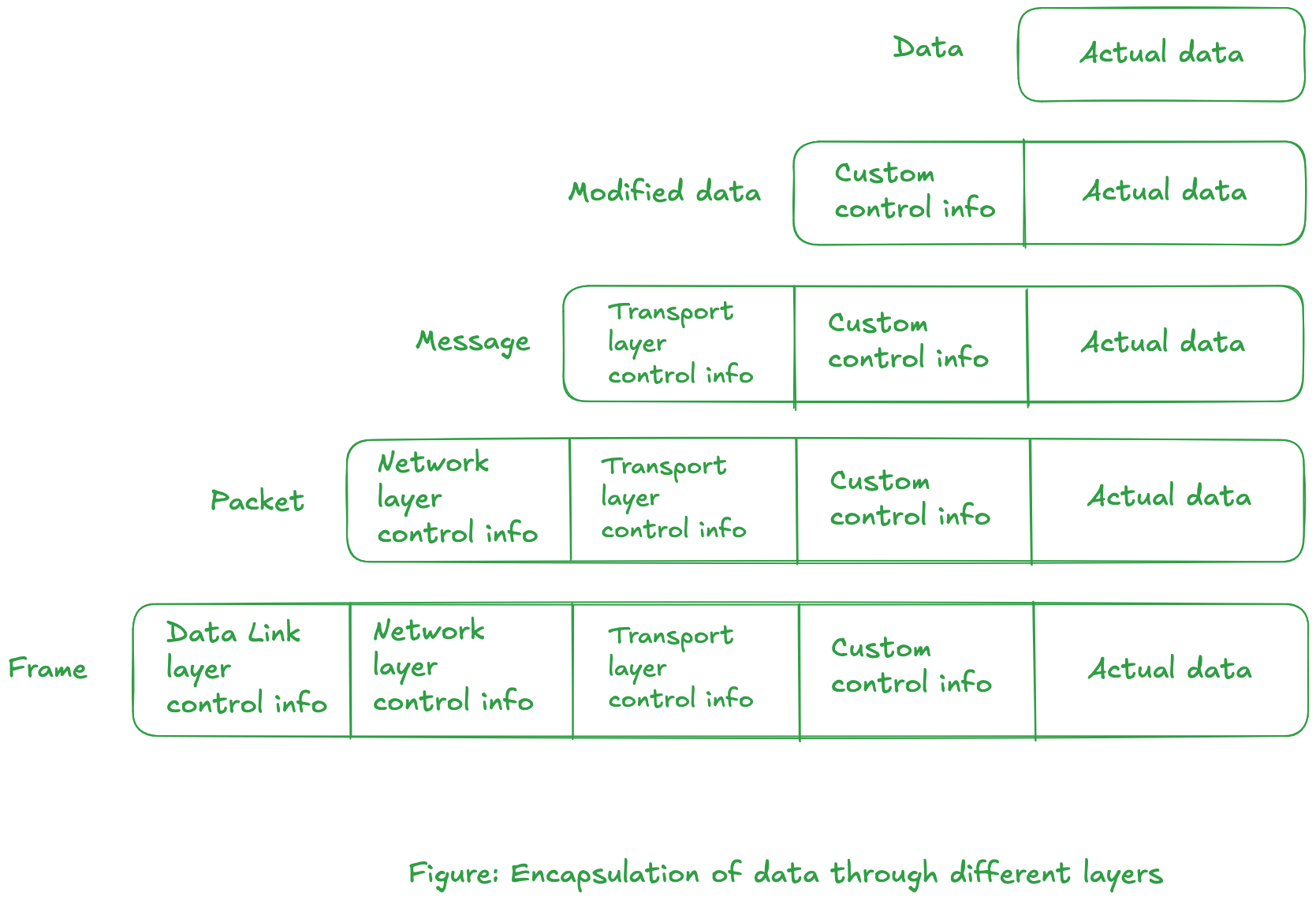
From the figure, the process layer deals with the "Modified data" portion while the information of lower level protocols are stripped down.
As the data is passed down, control information is prepended before the actual transmission takes place in data-link layer. -
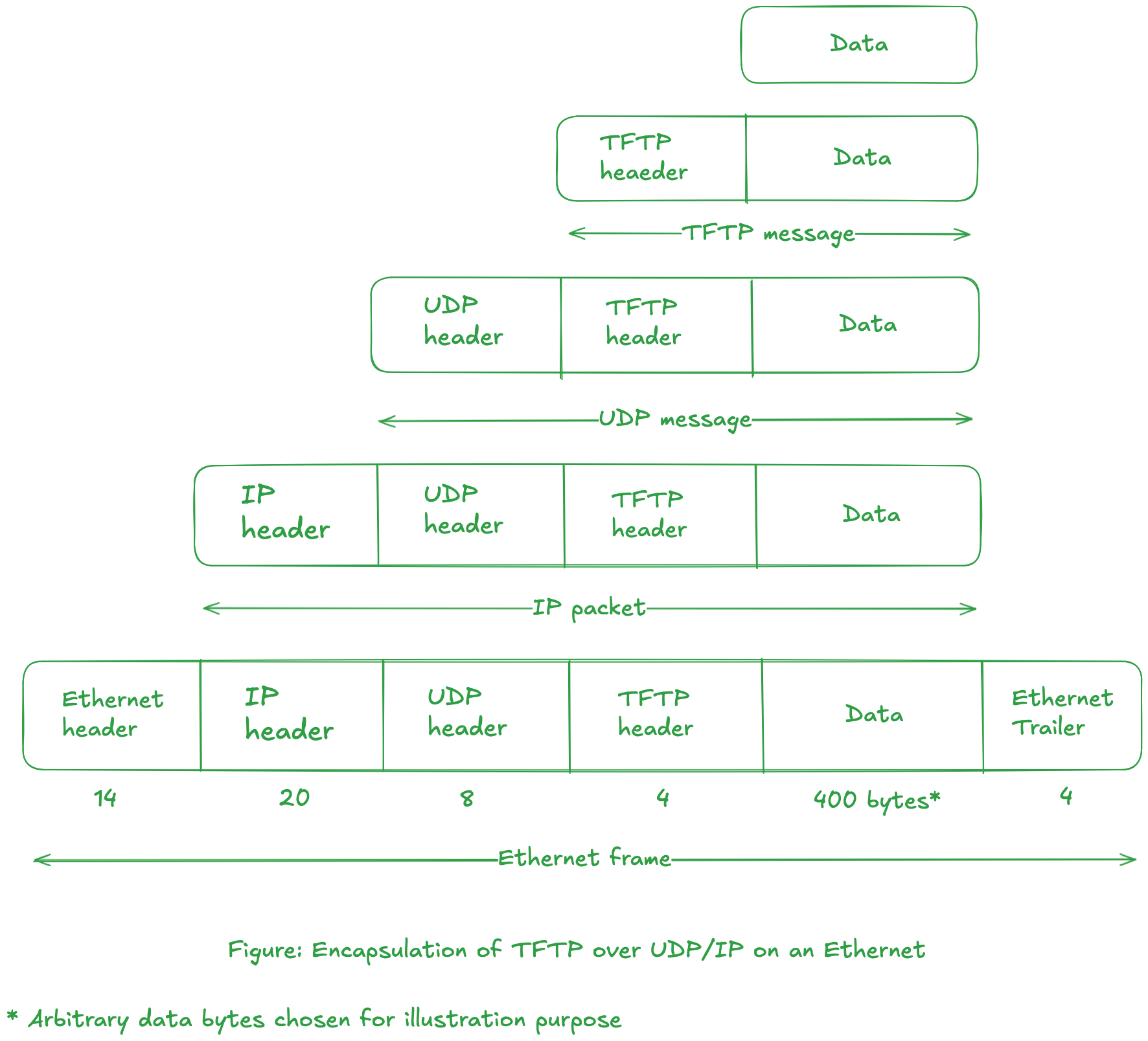
The figure below illustrates the various level of encapsulation for TFTP application.
-
TFTP client process adds 4 bytes of control information to the beginning of the data buffer. The modified buffer is sent to UDP layer. The UDP layer does not interpret the 4-byte TFTP header.
-
The task of UDP layer is to transfer 400 (arbitrary data length) + 4 = 404 bytes of data to the other UDP layer. The UDP layer prepends its own 8-byte header, passing 412 bytes of buffer to the IP layer.
-
The IP layer prepends it 20-byte header and passes the 432 bytes buffer to the data-link layer for the Ethernet.
variable ip headerWe assume that the header size is 20-byte. An IPv4 header can range from 20 bytes to 60 bytes. IP modules are--according to RFC 791--required to interpret the "options" field in IPv4 header. If this field contains additional information, the header size can vary upto 60 bytes.
-
At the data-link layer (for ethernet), a 14-byte header and a 4-byte trailer are added to the buffer of information.
-
The final diagram shows the Ethernet frame that is physically transmitted across the Ethernet, along with the sizes of each of the headers and trailers, in bytes.
-
Multiplexing and Demultiplexing
-
To multiplex is to combine many into one.
-
Consider a multihomed, multiuser computer system as shown below:
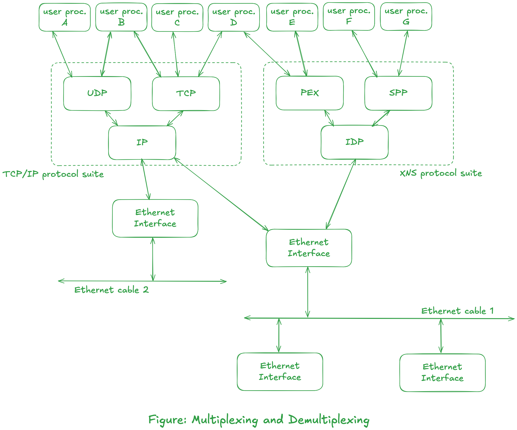
- Applications can use different protocol suite. We can also see that different protocol suite can use same Ethernet interface (as seen in cable 1.)
- Applications can use different protocols at the same time (like process B, and process D.)
- More than one user process at a time can be using any of the user accessible protocols (UDP, TCP, PEX, or SPP). The transport module must identify the user process (for example, A or B for UDP module) that is sending data when the UDP software passes this data down to the network module (for example, IP.) This is one example of multiplexing. Conversely, when the UDP module receives data from the IP layer, it must be able to identify the user process to receive that data. This is demultiplexing.
tipTCP or UDP provides 16-bit port number that identifies the user process.
- The IP module must determine the transport module which handles the data received from the ethernet interface. The IP header contains 8-bit protocol field for this purpose.
noteWe show the computer system with two Ethernet interfaces. This system is a gateway between two networks.
- The software (the device driver) for the interface connected to Ethernet cable 1 must determine if a received Ethernet frame is for the IP module or the IDP module.
tipThere is a 16-bit field in the Ethernet header that identifies the frame type. This allows multiple protocol suites, such as TCP/IP suite and the XNS suite, to share the same Ethernet.
- An Ethernet interface must determine if a frame that is being transmitted across the physical cable is for it, or for another interface. This determination is done by the Ethernet hardware. Each Ethernet frame contains a 6-byte address in its header that identifies the destination interface. Ethernet addresses are usually supplied by the hardware vendor so that every interface has a uniquq 6-byte address.
Packet Switching
-
A communication network can be differentiated into two categories: circuit switched and packet switched.
-
Regarding circuit switched network, consider the public telephone system. When you place a telephone call, a dedicated circuit is established for you by the telephone switching offices, from your telephone to the other telephone. Every telephone is directly connected to a local office, typically within a few miles of the phone. Local offices are then connected to toll centers, and these toll centers are connected together through sectional centers and regional centers. A figure below illustrates this:
 note
noteOnce the circuit is established, the only delay involved in the communication is the time required for the propagation of the electromagnetic signal through all the wires and switches. While it is sometimes hard to obtain a circuit, once the circuit is established you're guaranteed exclusive access to it.
-
A leased telephone line, which is common for WANs, is a special case of a circuit-switched network. But there is no setup required to establish a dedicated circuit between two telephones.
-
An Internet typically uses packet-switching techniques. Instead of trying to establish a dedicated communication line between one computer and another, the computers share communication links (sharing bandwidth). Instead, the information is divided into pieces and each piece is transmitted on its own through the connection of networks. These pieces are called packets.
A packet is the smallest unit that can be transferred through the networks by itself. A packet must contain the address of its final destination, so that it can be sent on its way through the internet (most protocols also specify that a packet contain the sender's address, too.) From previous sections, we can conclude that it is the network layer that is involved in transferring packets around the networks.
-
The communication bandwidth is reserved when it comes to circuit-switched network. For packet-switched network, however, we are sharing the communication bandwidth with other computers.
-
Packet-switching on LAN refers to multiple computers sharing a single communication channel, such as Ethernet or a token ring. Note that a dedicated link is not used between each computer. All the computers on the LAN share the available capacity of the network. (A WAN can also use packet-switching.)
-
Consider the internet(work) shown below:
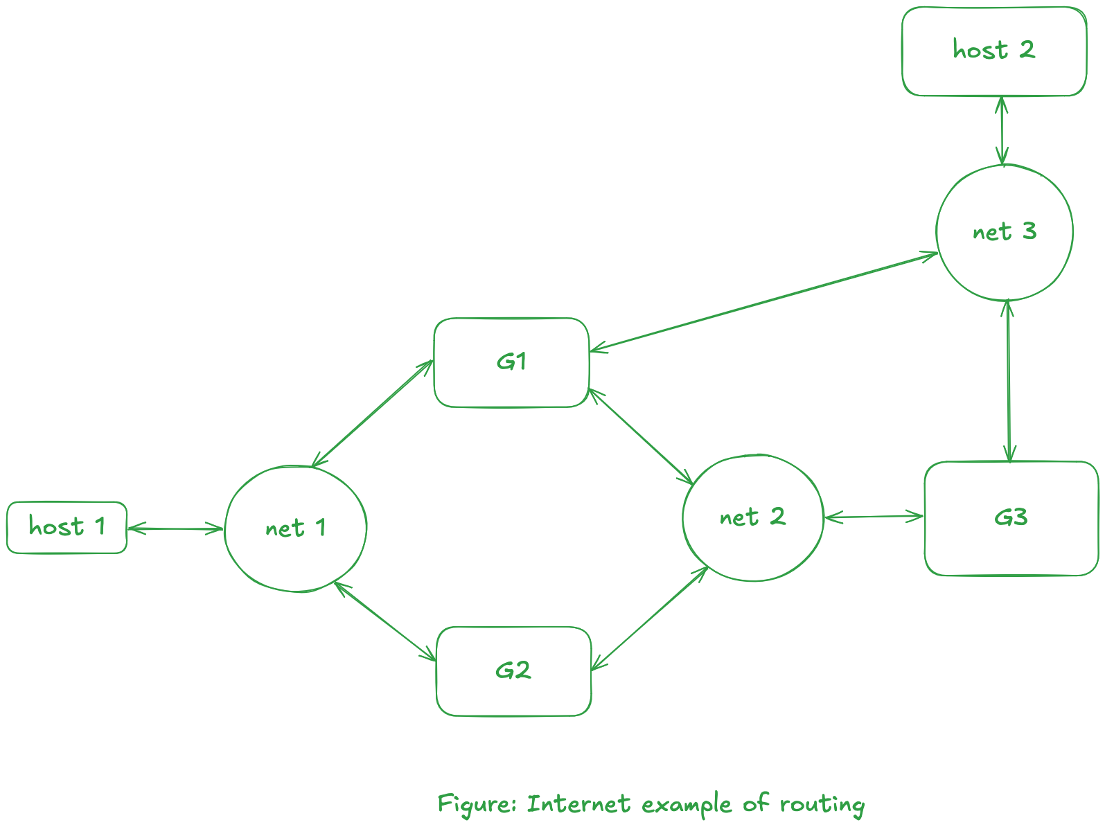
For the packet (from host 1) to reach to host 2, there are four possible acyclic paths:
- host 1 -> net 1 -> G1 -> net 3 -> host 2
- host 1 -> net 1 -> G1 -> net 2 -> G3 -> net 3 -> host 2
- host 1 -> net 1 -> G2 -> net 2 -> G1 -> net 3 -> host 2
- host 1 -> net 1 -> G2 -> net 2 -> G3 -> net 3 -> host 2
noteEach of these paths is called a route. Routing decisions are usually made at the network layer in the OSI model.
-
In a packet-switched network, there is no guarantee how long it takes a packet to go from one host to another. The time taken for each packet depends on the route chosen for that packet, along with the volume of data being transferred along that route.
Gateways
-
We previously mentioned thaa a gateway is a system that interconnects two or more networks. The function of a gateway is to pass along information from one network to another.
cautionThe layer at which a gateway operate depends on the type of translation and forwarding done by the gateway.
-
Consider that we have an internet of networks that all use the TCP/IP protocols, then no translation of protocols is required. Instead, each gateway only needs to forward packets from one network to another. Note: the IP layer is responsible for this forwarding of packets. An illustration is shown below:
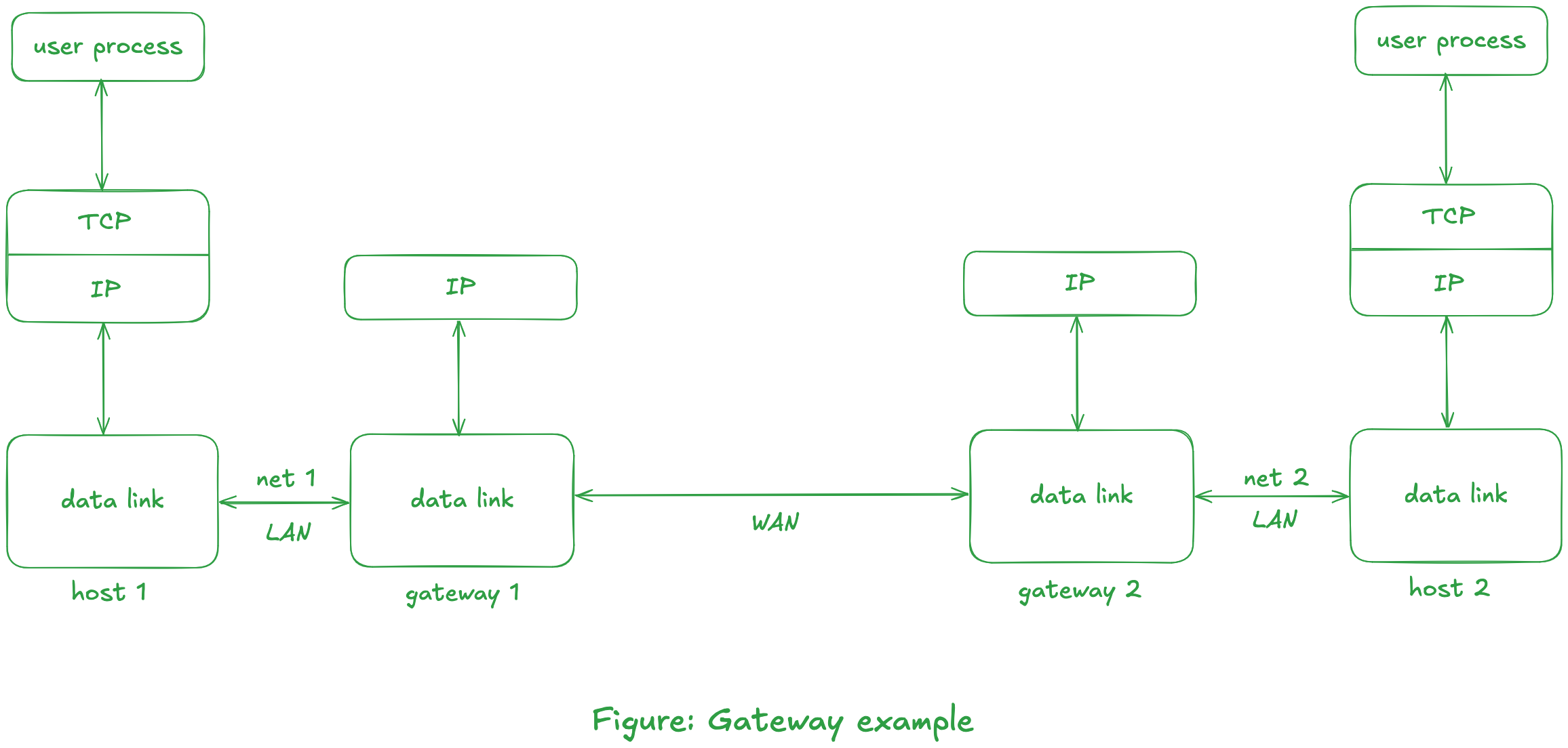
Each IP packet contains enough information (i.e., its final destination address) for it to be routed through the TCP/IP internet itself.
-
Things become more complicated, if we want a gateway between networks that use different protocol suites.
The conversion is often done in layers above the network layer.
Notice in the previous figure that the TCP layer is not needed on the intermediate gateways.
tipThe transport layer is the lowest layer that provides the virtual connection between the two hosts on which the user processes are runnning.
To understand packet-switching in a WAN, again consider the previous figure. Assume the two LANs are Ethernets and assume that the two gateways are separated by thousands of miles but are connected with a leased phone line.
Even though the leased phone line connecting the gateways is a circuit-switched connection, we still consider this a packet-switched network. This is because there are usually many hosts that share the Ethernets connecting each hosts and its gateway. UNP also mentions that the number of hosts on an internet typically exceeds the number of gateways on the internet by a factor of 10 or more. For example, the TCP/IP Internet is currently estimated to have over 150,000 hosts and 850 networks.
All the hosts on one of these Ethernets compete with the other hosts on that same Ethernet for the single link between the two gateways. Nevertheless, this arrangement is more reasonable than a leased phone line between every host on network 1 and every host on network 2.
Fragmentation and Reassembly
Exercises
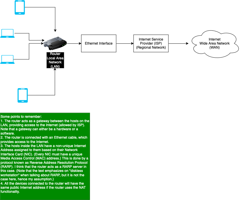
Question 4.1
Draw a diagram of the local area network that you have access to. Include hosts, repeaters, bridges, routers and gateways. Indicate what equipment (token ring, Ethernet, etc.) is being used at the physical layer.
- Answer
The diagram is shown below, which not only contains the local area network, but also the connection with the Internet that we know today. Also, note that on my local area network, no repeaters or bridges are being used. I believe the router used today also acts as a gateway rather than just routing the packets to the Internet.